Primary surface measurement reported
Chapter 3 reports droplet contact angle in the electrowetting system, showing 133° in the unwetted state and 15° at 3.6 V DC in the wetted state.
Client Citation Analysis
Chapter 3 reports droplet contact angle in the electrowetting system, showing 133° in the unwetted state and 15° at 3.6 V DC in the wetted state.
The equipment list names the instrument as “A digital tensiometer setup (Smartphone-based tensiometer, Droplet Lab Instrument, Canada),” used for accurate measurement and monitoring of the droplet.
The contact-angle data were used to characterize DC electrowetting performance in Configuration 1. Interfacial tension also appears in the Lippmann–Young model and in the surfactant rationale used to lower activation voltage, and the resulting wetting change is then connected to the device’s variable-IR appearance experiments.
Figure 13 states that the wetting process is fully repeatable.
The primary surface measurement reported in Chapter 3 is droplet contact angle during electrowetting. The chapter also frames the behavior through the Lippmann–Young equation, where interfacial tension, σlv, appears as a model parameter.
Capacitance was measured to estimate the thickness of the self-assembled lipid bilayer. Visible-appearance and infrared-appearance tests were also used to track droplet coverage, apparent temperature, and actuation behavior during electrowetting.
The thesis uses a digital tensiometer setup, cited as “A digital tensiometer setup (Smartphone-based tensiometer, Droplet Lab Instrument, Canada),” for direct observation of the electrowetting droplet in Configuration 1. The paper states that it was used for accurate measurement and monitoring of the droplet, that droplet images were captured by the embedded smartphone while the droplet was applied by the default threaded plunger syringe, and that the contact angle change upon wetting was determined using the digital tensiometer.
Within the chapter workflow, this contact-angle readout provides the wetting comparison between the unwetted and voltage-actuated droplet states used to characterize electrowetting performance for adaptive infrared camouflage.
The central Dropometer-derived result is the change in droplet contact angle from 133° in the unwetted state to 15° at 3.6 V DC in the wetted state. Figure 13 presents this side-by-side comparison and states that the wetting process is fully repeatable.
The thesis presents the device as a low-voltage electrowetting system, with nearly complete wetting reached at 3.6 V DC. The chapter also states that this voltage is much lower than what is observed in conventional electrowetting systems.
The water droplet contained 3 wt% SDS and the ambient dodecane phase contained 0.8 wt% sorbitan trioleate. The thesis states that SDS was added to the water to reduce activation voltage by lowering surface tension, and that the inclusion of surfactants decreased σlv significantly.
Capacitance measurements were used to calculate a lipid bilayer thickness of 4.928 nm. The chapter uses this result to support the interpretation that a very thin dielectric layer enables low-voltage actuation.
In the IR experiments, the droplet coverage increased upon wetting and the apparent temperature changed markedly when the droplet covered the reflective electrode. The thesis reports an average wetting actuation time of 1.00 ± 0.33 s and presents the electrowetting system as capable of adaptive infrared camouflage.
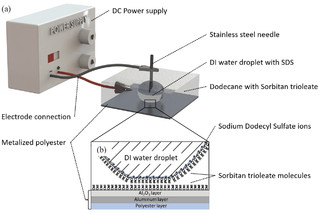
Figure 11 schematically shows Configuration 1, including the stainless-steel syringe tip, metalized polyester electrode, water/SDS droplet, and dodecane with sorbitan trioleate used for the contact-angle experiment.
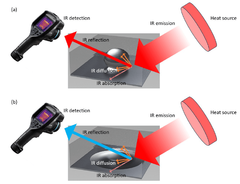
Figure 13 is the primary Dropometer-linked result, showing the droplet at 133° in the unwetted state and 15° after actuation at 3.6 V DC.
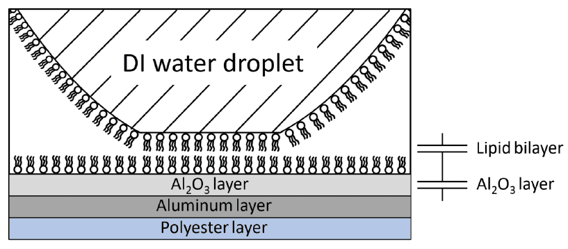
Figure 14 illustrates the droplet–electrode interface used in the chapter’s capacitance-based interpretation of the lipid bilayer and aluminum oxide layers.
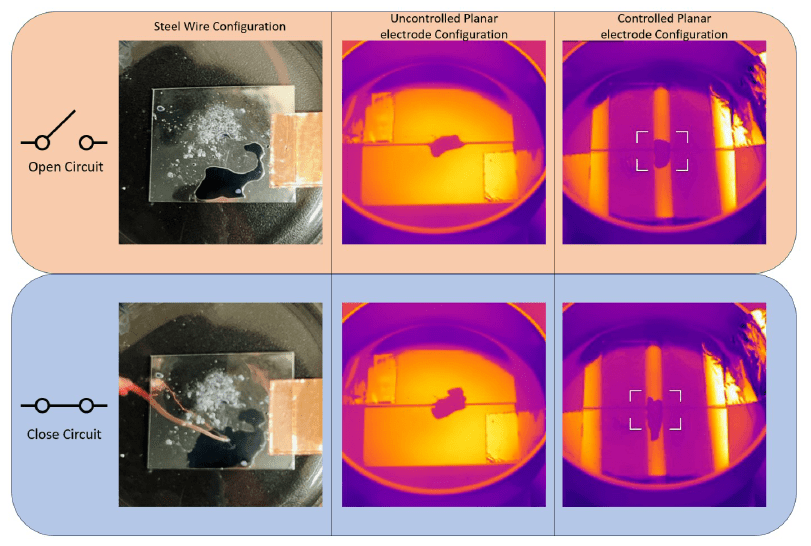
Figure 16 shows how electrowetting changes droplet coverage and reflected infrared appearance in the device configurations developed for adaptive IR camouflage.
Chapter 3 is framed around the feasibility of a low-voltage electrowetting device for adaptive infrared camouflage. In that context, the Dropometer-derived contact angle is the direct wetting metric used to show that the droplet moves from a hydrophobic state to nearly complete wetting under a small applied DC voltage.
That wetting change is then carried into the paper’s infrared interpretation. As the droplet spreads over the reflective electrode, the chapter uses the resulting coverage and apparent-temperature change to demonstrate variable IR appearance in the electrowetting system.
The equipment section credits the instrument as “A digital tensiometer setup (Smartphone-based tensiometer, Droplet Lab Instrument, Canada)” for droplet measurement and monitoring.
The Dropometer-supported output used in the chapter is contact angle, with the electrowetting comparison reported as 133° in the unwetted state and 15° at 3.6 V DC in the wetted state.
The contact-angle workflow uses a water droplet containing 3 wt% SDS in dodecane containing 0.8 wt% sorbitan trioleate on a metalized polyester electrode.
The thesis states that droplet images were captured by the embedded smartphone while the droplet was applied by the default threaded plunger syringe.
The paper specifies that sorbitan trioleate concentration must be over 0.1 wt% and that the water droplet must be applied after the electrode is submerged in dodecane.
In this work, the contact-angle measurement supports the development and characterization of a low-voltage electrowetting system for adaptive infrared camouflage.