
Conformal Coating Surface Prep for PCBs: Solder Mask, Cleanliness and Readiness for Every Type of Conformal Coating
Conformal coating protects circuit boards only when it wets and holds on a clean surface. Check water contact angle on your PCB assemblies before and after cleaning or plasma, against a known good reference, and catch flux residue and contamination before the coating is applied.
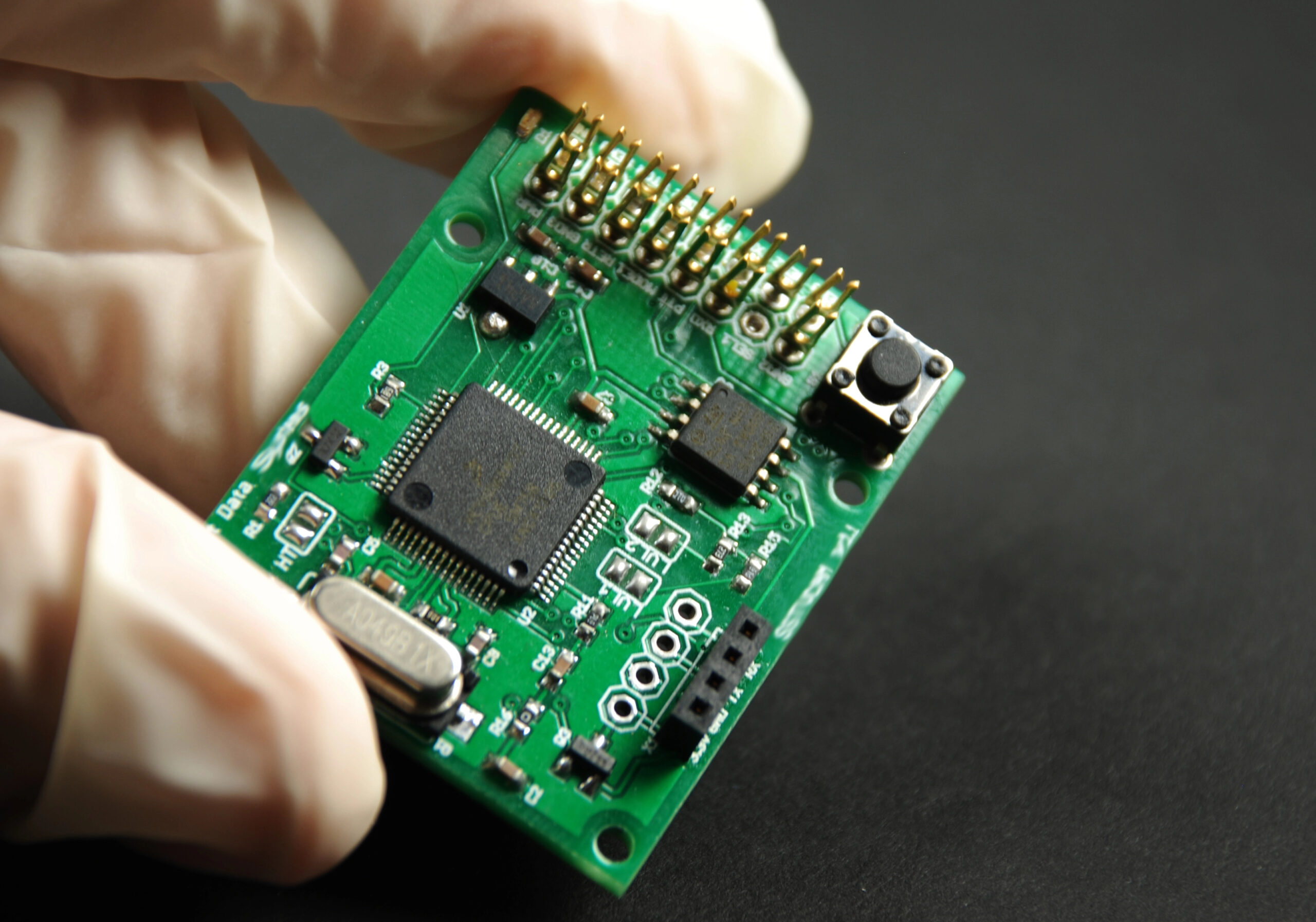
Who this is for: Process and quality engineers in PCB manufacturing and circuit board assembly who apply conformal coating, and the coating chemistry teams that support them.
Where it fits: Cleaning and plasma process setup, a readiness check in the application process before each conformal coating application, solder mask or flux changes, and root cause work on dewetting and delamination.
What it does not do: It does not measure ionic cleanliness, SIR, coating thickness or adhesion, and no IPC standard sets a contact angle limit for coating readiness.
Prof Rajan Ambat
Professor in Corrosion and Surface Engineering, Department of Mechanical Engineering, Danmarks Tekniske Universitet - DTU
Expertise in macro, micro- and nano-scale corrosion, electrochemical mechanisms and methods. Relation between microstructure and corrosion in engineering materials. Corrosion in Electronics. AI applications in corrosion research. Teaching and developing courses focusing on materials selection and corrosion.
Featured Studies & Publications
Why PCB surface prep decides coating reliability
Above 80° to below 15°
water contact angle on an unpopulated PCB before and after atmospheric plasma; the angle rose again from 8.5° to 24.3° within 40 minutes, giving about a 20 minute coating window.
Stumm, ANDA Technologies, 2019 (equipment maker data)
Up to 44.1 µg/cm²
weak organic acid flux residue on selective soldered PCB assemblies; coated wave and selective soldered boards blistered in high residue areas at 40 °C and 98% RH.
Conseil, Jellesen and Ambat, DTU, 2014
Sources: Hunt C., Zou L., A new method for measuring conformal coating adhesion, NPL, IPC APEX 2011; Stumm B., Atmospheric plasma treatment prior to selective conformal coating, ANDA Technologies, 2019; Conseil H., Jellesen M. S., Ambat R., contamination profile of printed circuit board assemblies, DTU, EuroCorr 2014, and Soldering and Surface Mount Technology 26(4), 2014. Figures come from these sources, not from Droplet Lab measurements.
What this PCB surface check does and what it does not
A quick reference for electronics coating teams checking fit before reading further.
Evidence Box
Conformal coating that dewets, fisheyes or delaminates on some boards, after a flux, cleaner, solder mask or plasma change, with no fast number on the board surface.
IPC-CC-830C qualifies coating materials; IPC-SM-840E and IEC 61086-1 leave board and coating compatibility to the user. No IPC-TM-650 method measures contact angle or surface energy.
The Dropometer drop shape method was validated against a KRUSS DSA100E in two peer reviewed papers, in Review of Scientific Instruments and Colloids and Surfaces A.
A global maker of plating and surface finishing chemistries for electronics manufacturing runs the Dropometer at two R&D sites, with custom PTFE parts for its harsh solutions.
NPL found contamination cut coating peel force, but water contact angle did not predict adhesion across different materials, so compare like with like.
Contact angle is a same surface comparison, not an adhesion test or an ionic cleanliness test. A static angle on a level board can differ too little between solder masks or light contamination; tilted board readings separate them better.
What conformal coating question are you trying to answer?
Pick the card closest to your role. Each one points to the part of this page that answers it.
Quality manager
A coated PCB fails inspection for dewetting, bubbles or delamination, or fails in harsh environments in the field. A water contact angle on each lot, against a reference board, shows whether the surface changed before the coating is applied.
Process engineer
You run cleaning, plasma and the conformal coating process: spray, dip coating, brush coating or selective coating. Contact angle before and after each step shows whether cleaning or plasma did its job, and how long the surface stays ready.
Coating chemistry or R&D
You choose between acrylic, silicone, polyurethane, epoxy, UV cure and parylene, or qualify a new solder mask or flux. Contact angle on each surface shows how coating selection and surface prep interact.
Is this the right check for your coating process?
It measures how water wets the board surface. It does not measure ionic residue or adhesion.
Good fit if
Less relevant if
How contact angle supports conformal coating surface prep
The answer in under a minute.
Measure water contact angle at marked areas of each PCB assembly before coating, against a reference board cleaned by your validated process. Static angles on a level board can differ too little to separate solder masks or light contamination, so also tilt the board and read advancing, receding and roll off angles. Readings outside your gate flag flux residue, silicone or handling contamination; confirm with SIR and adhesion tests.
The Dropometer contact angle kit runs the check. The IPC-TM-650 page covers the cleanliness and SIR methods, and the IPC J-STD-003 page covers solderability. A plating chemistry maker case study shows the kit at two electronics chemistry labs. Our article on contact angle for coatings and telecommunications guide add background.
Expert perspective on coating defects
Craters, fisheyes and orange peel are wetting stories told after the fact; measured surface tension and contact angle let you read the ending before you commit the coat.
Why conformal coating fails on circuit boards
Conformal coating is a protective layer that protects circuit boards and components from moisture, humidity, corrosion and contamination in harsh environments, from automotive electronics to aerospace. The common conformal coating types are acrylic, silicone, polyurethane, epoxy and parylene, which is applied by a vacuum deposition process, plus UV cure liquid coating chemistries. The conformal coating is applied by spray coating, dip coating, brush coating or automated conformal coating with selective coating machines, and the curing of conformal coatings depends on the coating type, with a curing process by heat, moisture or UV. Whatever the type of coating, it has to wet the PCB surface. Flux residue, silicone from mould release, handling oils and other contaminants lower the surface energy of the board, and the coating pulls back, fisheyes or later delaminates. Peer reviewed studies found that flux residues under coatings cause blisters, leakage current and dendrites in humidity. The standards leave a gap: IPC-CC-830C qualifies the coating material, solder mask qualification leaves compatibility with coatings to the user, and no IPC-TM-650 method measures contact angle. ROSE testing is a process control tool that does not predict reliability. Teams need a fast, local check that the surface is as ready as their good boards, before each coating application, to protect long-term reliability.
Why conformal coating defects happen and what to check
Why:
- No clean and selective soldering flux residues stay on the board and attract moisture under the coating.
How to detect:
- Water contact angle reads higher near each solder joint than on the reference board.
Corrective action:
- Review flux choice and cleaning, and confirm with ion chromatography and SIR.
Why:
- Silicone mould release, adhesive residue and skin oils give low energy patches the coating will not wet.
How to detect:
- The angle is high in patches rather than across the board.
Corrective action:
Control gloves, release agents and nearby silicone. Our sample prep and contamination control guide covers handling.Why:
- Cleaner, rinse or dry steps that drift leave residue across the board.
How to detect:
- The angle rises across all areas compared with the reference board.
Corrective action:
- Check cleaner concentration, temperature, rinse and drying, then remeasure.
Why:
- A freshly cleaned or plasma treated surface regains a higher angle within minutes to hours.
How to detect:
- The angle rises with time between cleaning or plasma and coating.
Corrective action:
Shorten the wait to coating. Our page on plasma treatment verification covers the plasma side.Why:
- Solder mask chemistry and cure differ between products, and compatibility with coatings is left to the user.
How to detect:
- The board reads clean, yet one coating dewets on one solder mask and not another.
Corrective action:
- Test coating selection on each solder mask and record the pairing that works.
Why:
Drop volume, read time and position change the reading. Our three phase contact line entry explains why edges matter.How to detect:
- A reference board reads differently between sessions.
Corrective action:
- Fix drop volume, read time and board map, and measure a reference board each shift.
Not sure why your coating dewets on some boards?
Send good and failed boards, and we will compare them on a call.
What a PCB surface readiness record contains
Each check produces a record you can file with the board lot, beside cleanliness, SIR and coating inspection results. It can feed into your existing quality records.
Board
PCB design, solder mask, flux, cleaning or plasma process and lot.
Timing
Minutes or hours since cleaning or plasma, and storage before coating.
Method settings
Drop volume, read time, board map, temperature and humidity.
Readings
Water contact angle at each mapped area, with median and spread against the reference board.
Decision
Coat, reclean or hold, and the coating inspection that followed.
Drop images
Automatic edge and baseline detection gives the same reading from the same image, so a reviewer can recheck any result.
What to measure before conformal coating
Water contact angle against a reference board
Why it matters: It shows whether this board surface matches boards that coated well.
How to interpret: No IPC standard sets a contact angle limit. Set your gate per board area, solder mask and cleaning process from boards that coated well and boards that dewetted.
When it is not enough: On a level board the static angle can differ too little between solder masks, or between clean and lightly contaminated areas. NPL also found water contact angle did not predict peel adhesion across different materials; compare like with like.
Angle by board area
Why it matters: Residue gathers near soldered joints and around components.
How to interpret: Compare laminate, solder mask and areas near parts on a fixed board map.
When it is not enough: Pads and very small areas may be too small for a drop.
Angle after cleaning or plasma over time
Why it matters: The surface becomes less ready as it waits.
How to interpret: Measure at fixed minutes after treatment and set the longest wait that stays in your gate.
When it is not enough: It does not show ionic residue that leaves the angle unchanged.
Published solder mask values
Why it matters: They show what a clean mask can read.
How to interpret: Published water contact angles for cured solder masks range from about 58° to 84°, depending on product and cure.
When it is not enough: Your own reference board decides; published values are context only.
Advancing, receding and roll off angles on a tilted board
Why it matters: Static angles on a level board can differ too little to separate solder masks, or clean and lightly contaminated areas. Tilting the board until the drop moves gives the advancing and receding angles and the roll off angle, which follow wettability more closely.
How to interpret: Compare each reading with the reference board on the same mask. A water repellent film usually raises the receding angle and lets the drop roll off at a lower tilt. Set gates from boards that coated well and boards that dewetted.
When it is not enough: The drop needs a flat run of a few millimetres, which crowded boards may not have. The Dropometer sliding angle add-on tilts the sample for this reading.
Validated measurement approach for PCB surfaces
How the Dropometer itself has been validated, and where it is used in electronics chemistry.
Peer reviewed method
The Dropometer drop shape method is published in Review of Scientific Instruments and Colloids and Surfaces A. Contact angle was validated against a KRUSS DSA100E, with a published accuracy of 0.35°.
See the validation papersCustomer evidence in electronics chemistry
A global maker of plating and surface finishing chemistries, mainly for electronics manufacturing, runs the Dropometer at a European wet chemistry lab and a US R&D lab. It measures water contact angle on substrates and surface tension of its own solutions, with custom PTFE parts for caustic liquids. More customer work is listed on our citations page.
Read the case studyHow to check PCB surface readiness before conformal coating
Six steps per board lot. Repeat after any flux, cleaner, solder mask or plasma change.
Lock the method
Fix drop volume, read time, tilt rate and a board map of flat areas on solder mask and laminate.
Make a reference board
Clean a board by your validated process and measure it each shift. Compare with our contact angle reference values.
Clean or plasma treat
Run your process and note the minutes since cleaning or plasma.
Measure the map
Place drops at each marked area away from tall parts, and record median and spread. On a sample of areas, tilt the board until the drop moves and record the advancing, receding and roll off angles; our sliding angle measurement guide explains the reading. Our treated versus untreated surfaces experiment shows the effect of treatment.
Decide
Compare with your gate, then coat, reclean or hold.
Confirm after coating
Inspect for dewetting and log the result with the reading. Our guide to the best contact angle goniometer for industrial QA covers routine use.
We completed our gage R&R study on the unit and it performed very well.
Brandon Barbee
Corporate Quality Engineer, Zeus Industries, Polymer Manufacturing
Download the PCB surface readiness SOP
A two page SOP you can adapt for your boards, with the method lock, a board map, how to set a gate against your coating results, a troubleshooting table and a record sheet.
Contact angle measurement with the Dropometer
Example PCB surface readiness log
Example data only. Your values and gates will differ and must come from your own coating results.
Example gate: no more than 8° above the reference board at any area. Lot 1 matched the reference and coated well. Lot 2 read high near soldered areas, pointing to flux residue. Lot 3 was cleaned correctly but stored uncovered for two days, and the angle rose past the gate everywhere.
Example PCB surface readiness log
| Lot | Process | Solder mask area (°) | Near solder joints (°) | Laminate (°) | Coating result |
|---|---|---|---|---|---|
| Reference | Validated clean | 62 | 64 | 60 | Coated well |
| 1 | Validated clean | 63 | 66 | 61 | Coated well |
| 2 | No clean flux, not cleaned | 70 | 84 | 66 | Dewetting near joints |
| 3 | Validated clean, stored 2 days uncovered | 72 | 75 | 70 | Fisheyes at edges |
Example data, not customer data. Acrylic conformal coating by spray; 1 µL water drops read at 2 s; median of 3 drops per area.
The order to check signals before coating
Check these in order. Each one rules out a cause before you look at the next.
Method and reference board
Rules out timing, drop size and handling effects.
Angle across the map
Shows whole board cleaning problems.
Patches near joints and parts
Shows flux residue or local contamination.
Time since treatment
Shows recontamination before coating.
Ionic cleanliness and SIR
Confirms what water cannot see. Our electrical and electronics guide covers the wider picture.
Common questions about conformal coating and PCB surface prep
Questions electronics teams ask about coating application, cleanliness and contact angle.
What are the types of conformal coating?
IPC-CC-830C lists acrylic, epoxy, silicone, polyurethane and parylene, plus ultra thin and styrene block copolymer types. Acrylic conformal coating is easy to rework, silicone conformal coating handles a wide temperature range, polyurethane conformal coating resists moisture and chemicals, and parylene is vapour deposited. UV cure is a cure mechanism rather than a separate type. The right conformal coating depends on extreme temperature, chemicals and whether coating removal for rework matters, and the properties of the coating then set thickness and cure.
Why does conformal coating dewet or fisheye?
The coating cannot wet a surface with lower surface energy than it needs. Flux residue, silicone, handling oils and other contaminants create those low energy areas, so the coating pulls back or forms fisheyes around them. Cleaning and plasma raise surface energy, and a contact angle check shows whether they worked on each lot.
Does an IPC standard set a contact angle limit?
No. We found no IPC or IEC document that sets a contact angle or dyne level for coating readiness, and no IPC-TM-650 method measures it. The only contact angle in J-STD-003 is the solder fillet angle. Our IPC-TM-650 page covers the cleanliness and SIR methods that do exist.
Does contact angle predict coating adhesion?
Not across different materials. An NPL study measured water contact angle on laminate, copper, resists and components and found no correlation with peel adhesion, though contamination clearly cut peel force. Use contact angle to compare the same board surface before and after cleaning, lot to lot, or against a reference board. Advancing and receding angles on a tilted board separate surfaces more clearly than one static angle.
Is ROSE testing enough?
IPC-TM-650 2.3.25 says ROSE does not predict reliability and should only be a process control tool, and it misses non ionic residues. J-STD-001 asks for objective evidence that cleaning and soldering processes leave acceptable residues. Contact angle adds a fast surface check; SIR and ion chromatography stay the reliability evidence.
How long after plasma should we coat?
As soon as your process allows, and measure to find out. In one equipment maker's study, plasma dropped a PCB from above 80° to below 15°, then the angle rose from 8.5° to 24.3° within 40 minutes, with about a 20 minute coating window. Your window depends on your boards and room.
What coating thickness is typical?
J-STD-001G, as cited by ACI Technologies, gives 0.03 to 0.13 mm for acrylic, epoxy and urethane, 0.05 to 0.21 mm for silicone and 0.01 to 0.05 mm for parylene. Check the current revision and your drawing, which takes priority. A thicker coating does not fix poor wetting.
Which instrument do we need?
One that measures water contact angle with small drops on flat board areas at fixed read times, and that can tilt the board to read advancing, receding and roll off angles. The Dropometer does both, with its sliding angle add-on for the tilted readings, and a plating chemistry maker uses it for electronics chemistry at two sites. Our contact angle measurement guide explains the method.
What changes when you check boards before coating
Typical changes in how teams work. Benchmarks are given only where a published source exists.
Before and with PCB surface readiness checks
| Metric | Before Dropometer | With Dropometer | Indicative Benchmark |
|---|---|---|---|
| Coating readiness | Visual check only | Contact angle against a reference board | No IPC limit exists; set your own gate |
| Contamination | Found as dewetting after coating | High or patchy readings flagged before coating | Peel force 37 N to 12 N at 3% surfactant (Hunt and Zou, NPL, 2011) |
| Plasma timing | Fixed by habit | Coating window measured | 8.5° to 24.3° within 40 min after plasma (Stumm, ANDA, 2019) |
| Flux changes | Found in humidity testing | Areas near joints compared before coating | Blisters in high residue areas at 40 °C, 98% RH (Conseil et al., 2014) |
See the measurement on your own boards
Send good and failed boards. We will show the comparison on a call.
Estimate avoided rework from conformal coating defects
Enter your own numbers. The result is an estimate, not a Droplet Lab claim.
Conformal coating estimate
Estimate the value of catching board surface problems before conformal coating.
Result
Monthly savings = preventable rework cost + preventable scrap cost + other monthly savings.
What contact angle cannot tell you about PCB cleanliness
Honest limits, so you know when to reach for another test.
Contact angle shows whether a board surface matches your good boards before coating, as one part of a conformal coating solution for PCB protection. Ionic cleanliness, SIR, coating thickness, adhesion and electrical reliability need their own tests.
Standards, evidence and related electronics workflows
These pages cover the IPC methods, a customer example in electronics chemistry and related surface prep checks.
Standard
IPC-TM-650
Cleanliness, SIR and other IPC test methods.
Standard
IPC J-STD-003
Solderability of printed boards.
Case study
Plating chemistry maker
Two electronics chemistry labs, one setup with PTFE parts.
Instrument
Dropometer
Contact angle and surface energy.
Related use case
Functional, medical and electronic coatings
All functional coating use cases in one place.
Related use case
Wafer cleaning and photoresist adhesion
Surface checks before photoresist.
Related use case
Plasma treatment verification
Checking plasma before bonding and coating.
Guide
Telecommunications guide
Surface science for telecom hardware.
How this page was created
Editorial and technical transparency notes for this page.
Drafting assistance
Drafted with Claude Opus 5.5 (Anthropic) using web search for sources, then edited by the Droplet Lab team.
Technical review
Expert feedback from Prof Rajan Ambat (Technical University of Denmark, CELCORR) on the limits of a static angle on a level board and on adding tilted board advancing, receding and roll off readings. Edited by the Droplet Lab Team.
Verification steps
Standard identifiers, units, thresholds and key procedural claims are checked against cited sources before publication.
Updates
Reviewed every 12 months or when the underlying method changes.
Report a correction
Spotted an issue in this summary? Send a correction request and our team will review it.
Correction Request
We work hard to keep this page accurate and up to date. If you spot an error (wrong revision/year, missing requirement, incorrect interpretation, or broken link), tell us and we'll review it.
Contact us to report a correction